It has been a while since my last post, but I have actually been done with my keyboard for some time. Now that I have a moment, I will finally post the update!
Here is the final layout I settled on:

I have been using and tweaking this layout for close to 4 months now, and it is getting close to how I think I will leave it. There is still some fiddling to do with how mode works and some of the symbol keys, but overall, it is really close.
Here are some pictures of the final product:


Ah, ain't she pretty!
So, for those who really want to know, here is the step-by step building process:
Step-By-Step Build
Step 1 - Design
I feel like I have beat this dead horse enough... go check out parts 0 through 2 for this step. Overall I mostly used http://www.keyboard-layout-editor.com/ in the end. I started with other tools, but this one is just faster and easier to mix things around.Step 2 - Laser-Cut the Acrylic Case
I got access to the laser cutter up on campus. They let anyone get swipe-card access, so long as you fill out the paperwork. Hopefully you have some way to get access like this, it is an amazing machine that is super fun to use.If you cannot get access to a laser cutter, you can always have the parts made for you by a company that does laser cutting. That will, of course, be more expensive.
To laser cut your piece, you simply need to make a vector graphics image of what it should cut. The laser cutter here would cut all the way through for "hairline" lines, and then do etching for any kind of gradient. I wanted to get mine done quick, so I stuck with all hairline cuts.
Here is what my vector image looked like:

*See the apendix if you want the inkscape file
The layers stack starting in the bottom left, moving up the left column, and then going from bottom to top on the right column. I will refer to them by their number, starting with 1 as the bottom piece.
Layer 1 through 5 (the left column) and layers 7, 9, 10, and 11 were all cut into 0.06 in. (1.5mm) acrylic. (I used "12in. x 48 in. Acrylic Wire Shelf Liner (4-Pack)" for $31 from home depot.) I made duplicates of layers 9 and 11. (9 as a backup, since that's the most important piece, and 11 so one could go above, and one below the suit piece of layer 10.)
Layers 6 and 8 were cut into a spare piece of acrylic that was about 0.22 in. (5.6mm) thick. These layers are the main support layers for the switch mounting layers (7 and 9.) WARNING: Without these support layers, the switch mounting plates will break. I broke one just pushing the switches in and pulling them out a few times as I played with different switch profiles. You may be able to cut the support layers out of the same one you used for all other layers, and just double them up. I don't know, though, as I have not tried it.
Here are some pics of the final cut layers (Note, there is a tab in the top center of some of these, I removed that later and put in another key. It was a last minute change, but I designed it so I could do that. I was going to have my indicators top center, but changed my mind. Also note that I did not originally laser-cut the corner wholes in. I tried that later and it totally worked! Really well too!)
The thinner layers 1, 2, 3, 4, 5, 7, 9, 10, and 11:

Switches mounted on layers 7 and 9:

A stack of the thinner layers (top view on top, bottom view on bottom):


(I apologize, apparently I don't have pictures of just the thick pieces... oh well)
After cutting out all the layers, I found the posts I wanted at ace hardware and bolted it all together:


Step 3 - Soldering
This part takes, by far, the longest.
To save some cash, I just grabbed the nearest CAT5 (Ethernet) cable and pulled that apart. That gave me plenty of colors to work with for dirt cheap! You will also need some diodes if you wish to stop the ghosting effect (explained here, if you care...)
I recommend following the first few steps in the excellent guide created by matt3o on deskauthority.net found here:
Perhaps one day I will rewrite that part here for the sake of completeness, but I don't think I will today.
NOTE: When following the guide above, try to make sure you do your rows all the way across and your columns all the way down. I thought I would save some pins by trying to make mine as close to a square as possible. I ended up wiring the left and right halves as separate rows. While I saved some pins, it really just made the firmware step more complex and ugly. I was going to use the extra pins for some LED's but sticking to the rows and columns would have been just fine.
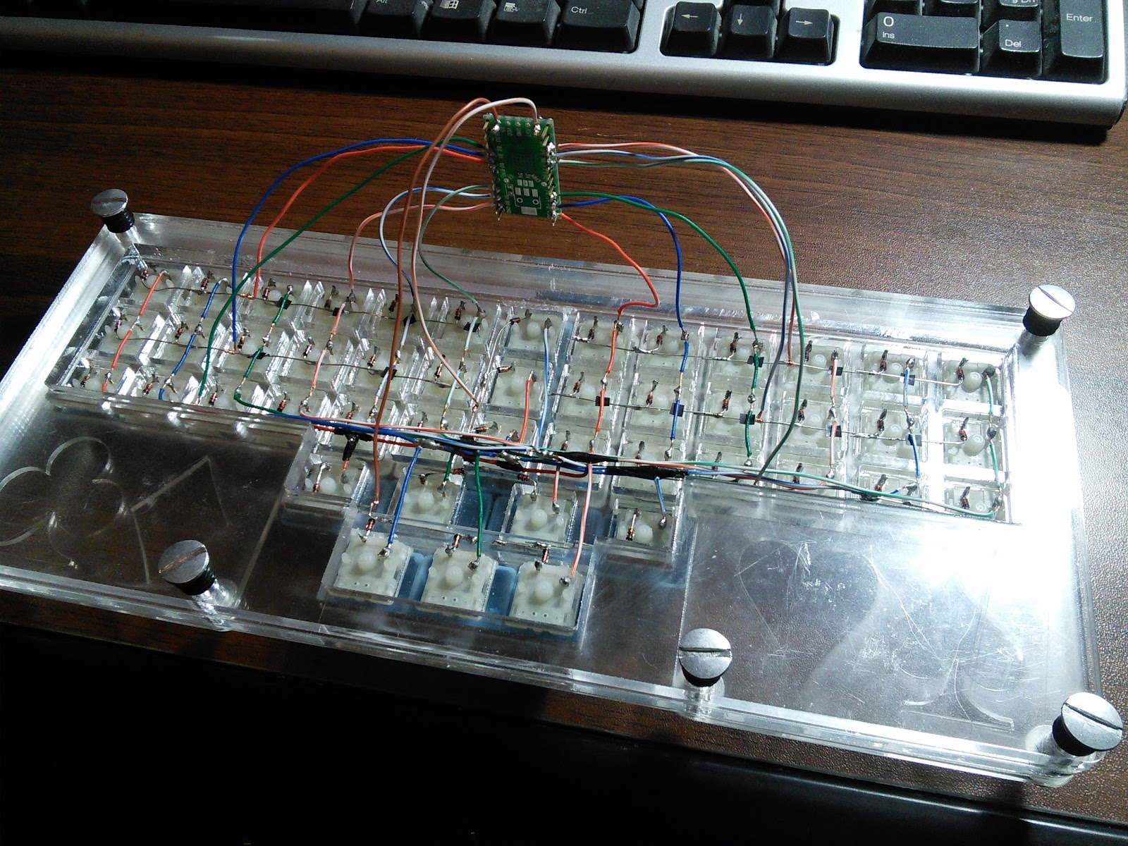
Here is a photo of my final wiring (Yeah, not toOOoo pretty, but I am a coder, not a hardware guy...)

Once all the columns and rows are soldered up good, you need to attach them to your microcontroller. Again, I used the Teensy 2.0 from PJRC. (That is what the firmware section below is aimed at too, so you might want to just use that one, unless you know what you're doing.)
Wire each row to a pin and each column to a pin on the Teensy 2.0.
NOTE: I messed up here again. I was looking at the keyboard upside-down for so long, that I forgot that I was looking at things backwards. I lined up my pins so nicely to follow a numerical, logical order, only to discover that they were all backwards. This doesn't matter too much, however, since the firmware has you put in the row-pin col-pin assignments. So... don't over think it. Just make sure you know what is hooked where.
Here are some pics of the teensy wired into the my keyboard:

And, putting it all together:

Note that I also ended up drilling a small (poorly lined up) whole in the bottom of the keyboard for quick access to the Teensy reset button. This made tweaking the firmware much faster, easier, and safer, as I didn't have to keep taking the thing apart anymore.
Step 4 - The Firmware
Surprisingly, this part was pretty easy. I had no soldering errors, so that helped, but overall, most of the work is done for you.
Once again, I would like to turn you over to matt3o. He has a great guide on using the TMK keyboard firmware:
Part 2: https://deskthority.net/workshop-f7/how-to-build-your-very-own-keyboard-firmware-t7177.html#p141386
Again, I may return to write up my own guide for the firmware, but for now, this suficeth me.
Step 5 - PLAY!!!
It's alive!
Now you can put away that old T.Oliver and be a high roller with your crazy custom keyboard (You are making an AlphaGrip, aren't you?)
If you do make one, send me a pic! I would love to see it.
Appendix
matt3o's guide. (I used this for most of the process. Thanks matt3o!)
Part 1: https://deskthority.net/workshop-f7/building-a-custom-keyboard-from-the-ground-up-t5761.html
Part 3: https://deskthority.net/workshop-f7/how-to-build-your-very-own-keyboard-firmware-t7177.html#p141386
- This has all the dimensions of the switch. There are two main types, plate mounted and pcb mounted. If you are doing the method above, you want plate mounted. (The pcb mounted ones do not have the clips to hook into a plate, but are fastened purely by soldering them to a PCB.)
- Many other switches have the same profile. I used Gateron switches, which fit perfectly into the cherry-cut slots.
Laser Cutter file for inkscape (SVG) (CC Non-commercial share-alike, contact me if you want commercial license. I will let you have it for free, I just want to know when commercial folks are using it.)
- Some laser cutters don't like Inkscape files. I had to export the file as a pdf, then import the pdf into Corel Draw. From there, I ungrouped the items and changed all lines to "hairline" in Corel Draw. After lining things up with how I wanted them on the piece, they were ready to print!
Teensy 2.0 Purchase Page
Teensy 2.0 Pinout Sheet (PDF)
No comments:
Post a Comment